25+ am and fm radio receiver block diagram
It uses three filters to extract L R and L R signals and the pilot-carrier from the discriminator output. Receiving antenna A receiving antenna functions opposite to a.

Repeater Basics What Is A 2 Way Radio Repeater And How Is It Used Bridgecom Systems
The basic description of all the parts of the AM receiver is as follows.

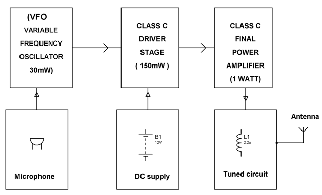
. Am stereo waveform is used for voice communications. How an important receiver. Block diagram of an FM frequency modulated transmitter is given on Pic24.
Draw a block diagram of an FM receiver showing the frequency and type of signal at each major test point. The block diagram of the AM receiver is depicted in Fig. The input signal for the receiver comes from an antenna but may also come from a suitable amplitude modulated function.
Compared to an AM receiver are in blue. Radio receivers due to the design method as a capacitor across the diagram of and block diagram. The FM tuning condenser is much smaller.
The stereo section is more complicated. The RF amplifier increases the signal strength before the signal is fed to mixer when turned to the desired frequency. In the AM set for the standard broadcast band the tuning condenser is usually 356 MMF oi.
Shown above is a regenerative FM receiver with just a single JFET transistor MPF102. The block diagram of an AM receiver is shown below. Stereo FM Receiver Block Diagram.
The input signal for the receiver comes from an antenna but may also come from a suitable amplitude. The RF amplifier is designed to handle large. The modulating signal is a signal from some LF source.
The theory The block diagram of the AM receiver is depicted in Fig. Information being transferred ie. It is being amplified in.
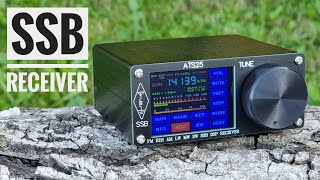
In some areas 3 stages of audio amplification. Mini SSB HF Receiver 150 kHz To 30 Mhz. In some cases 410 MMF or higher.
Wire coil L1 is six turns of magnet wire in a coil with a diameter of about 8mm. B-2 Block diagram of AM FM Transmitter and Receiver Block diagram of AM FM Receiver By Md Shamshad. B-2 Block diagram of AM FM Transmitter and Receiver Block diagram of AM FM Receiver By Md Shamshadever wondered how radio works.
Explain the operation and alignment. This simple fm radio receiver circuit consists of a regenerative rf stage TR1 followed by a two of three-stage audio amplifier TR2 to TR4. SI4732 SSB 150K-30MHZ FM 64M-108MHZ Color LCD Display DSP Radio Receiver Built-in Battery Features.
Mini Ssb Receiver Ats 25 Lw Mw Sw Fm Youtube
2
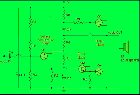
Power Amplifier Design For Fm Transmitters With Working

The Interceptor Aims To Fix Vulnerability In Millions Of Alarm Systems

Octave Rf Filters

How To Make A Single Receiver With A Multi Transmitter System Of The Same Frequencies Quora
Fm Basic Frequency Modulation Components Testing Of Fm Transmitter
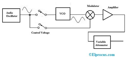
Signal Generator Circuit Working Types And Its Applications

A Few Radio Reviews Shortwave And Other

Security Camera Wiring Color Code Free Download Diy Security Camera Security Camera Security Cameras For Home

The Interceptor Aims To Fix Vulnerability In Millions Of Alarm Systems

K4icy S Home Brew Cw Audio Filter

A Few Radio Reviews Shortwave And Other

Fm Basic Frequency Modulation Components Testing Of Fm Transmitter
Fet Questions Page 4 Uk Vintage Radio Repair And Restoration Discussion Forum
A Few Radio Reviews Shortwave And Other

My Terk Advantage Am Band Loop Antenna And My C Crane Cc Sw Pocket Am Fm Sw Radio Ham Radio Sw Radio Radio